Introduction
The NASA Surveyor Program sent seven spacecraft to the Moon. Nearly 90,000 images were taken by five successful Surveyor spacecraft. In 2014, one of the original Surveyor mission scientists, Justin Rennilson, contacted the Space Imagery Center to inquire about digitizing the Surveyor images. In 2015, a grant was funded for the digitization and cataloging images for the Planetary Data System (PDS).
Foreword
The following is extracted from the Springer International Publishing AG 2018B. Cudnik (ed.), Encyclopedia of Lunar Science in part with editing and addition of reports by Justin J Rennilson a NASA/JPL appointed co-investigator on the Television Experiment.
The Surveyor Program
The five Surveyor spacecraft that landed safely on the Moon provided scientific data about the lunar environment, composition, and chemistry that paved the way for all the lunar missions to follow. This website summarizes the spacecraft design and history including a summary overview of the three science-specific payloads– television, the soil mechanics and surface sampler, and the alpha scattering instrument. The Surveyor spacecraft incorporated a Survey camera designed to serve as one in a suite of scientific instruments to carry out scientific measurements of the lunar surface along with stellar and Earth observations. The television provided essential observational support to the spacecraft and the corollary science from the Surveyor Spacecraft Subsystems.
History
Since 1936, rocket investigation under Dr. Malina had begun in the area of Pasadena called Arroyo Seco. In 1944 in that area, the Jet Propulsion Laboratory (JPL) was built. In 1961 NASA’s planning called for a lunar impact vehicle on the moon resulting in the Ranger program. That project designed, built, and operated the Rangers at the Jet Propulsion Laboratory.
The Surveyor program was devised to continue where the Ranger Program left off and produce spacecraft to make soft landings on the Moon. NASA in 1960 gave the direction of Surveyor to JPL (administered by the California Institute of Technology). Because of difficulties during the Ranger program, NASA directed the construction of the spacecraft to be awarded to an outside corporation. The Space Systems Division of the Hughes Aircraft Company received the final contract in 1961. The Atlas/Centaur rocket combination was designated as the launch vehicle. In the early years of the Surveyor program, the design was very expansive with tens of instruments and four television cameras. However, the second stage Centaur had serious problems using liquid hydrogen and oxygen as fuel, and the resulting payload was reduced from 2500 to 2100 lbs. That result meant dropping almost all instruments and leaving only two cameras. The launch date had been estimated as 1963/1964 but was delayed more than two years.
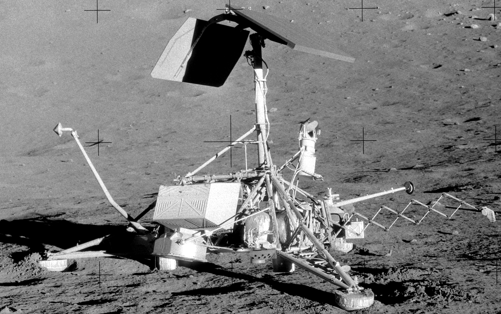
Hughes Space System Design
Each Surveyor carried instruments to evaluate spacecraft performance and landing characteristics and a television camera to secure detailed pictures of the immediate area in which it landed. In later missions, the payload also consisted of scientific instruments to determine lunar surface physical details. The spacecraft weighed approximately 2150 pounds (975 kg) and stood about 10 feet (3.04 m) high and within a circle about 14 feet (4.26 m) across. It has a triangular frame with a landing leg on each of the three corners. A solid-propellant retro-rocket engine fits within the center cavity of the frame and provides the main thrust for slowdown when approaching the Moon. A planar antenna and solar cell panel are mounted on a vertical mast at the top of the spacecraft. The telecommunications, flight control, and power supply units, as well as the payload items, are mounted in numerous packages around the frame to meet balance and operating requirements. The spacecraft did not need to be streamlined because it was enclosed within a conical shroud at the top of the Centaur until it left the earth’s atmosphere. As designed, control of the spacecraft was from the Earth, though certain landing operations were preprogrammed. Commands to the spacecraft were sent, and data was received by NASA’s Deep Space Network from stations in California, Australia, South Africa, and Spain so that line-of-sight communications were possible at all times. Central control of the mission was maintained at the JPL Space Flight Operations Facility (SFOF) in Pasadena.
Launch and Landing Operations
Within minutes after launch, when the spacecraft had emerged from the earth’s atmosphere, the enclosing Centaur shroud was ejected. At the end of the boost, the spacecraft’s legs and two omnidirectional antennas are extended, and radio signals are transmitted to facilitate tracking. The spacecraft then separates from Centaur and coasts along a trajectory that takes it to the near vicinity of the Moon. During coast periods the spacecraft provides (1) optimum illumination of the solar panel for battery charging, (2) optimum utilization of the spacecraft temperature control provisions, and (3) a reference attitude from which to orient the spacecraft for the midcourse and terminal descent maneuvers. The sun and star Canopus are the two attitude references. The sun is acquired initially by a broad space field-of-view sensor on the solar panel. With its vertical axis pointed toward the sun, the spacecraft was rolled until the Canopus sensor acquired the star. Thereafter, attitude control was automatic in response to error signals from the sun and Canopus sensors. The small thrust for attitude control was supplied by nitrogen jets mounted on each landing leg. This midcourse maneuver was performed about 15 hours after launch. When the spacecraft was about 1000 miles (1609 km) from the Moon, it was rotated on command from Earth so that the retro thrust line was in the direction of travel. The downward-looking television camera was operated at this time to supply in-flight pictures of the lunar surface. At the 60-mile (96.5 km) point, the Radar Altimeter and Doppler Velocity Sensor (supplied by Ryan Aeronautics) took over for the final minutes of the landing. Identical systems were used on each flight. These systems consisted of four narrow beams, at a wavelength of 2.3 cm, three of which were oriented at angles of 25°to the mean surface, and beam 4 was approximately at normal incidence. The altitude marking radar provided a signal to start both the Vernier propulsion system and the main solid-propellant retro-engine. The three Vernier engines had variable thrust and controlled spacecraft attitude in response to signals from the inertial gyroscopic reference unit. During retro burning, spacecraft velocity was reduced from 9000 (2753 m/s) to about 350 feet per second (105.7 m/s) as the spacecraft descended to about 25,000 feet (7520 m). The empty retro-engine was ejected after burnout. In the next phase of descent, the Vernier system slowed the spacecraft and controlled its attitude in response to a three-beam Doppler velocity sensor. At about 13 feet (2.96 m above the Moon’s surface, with speed reduced to about 5 feet per second (1.52 m/s), the Vernier system was shut off and the Surveyor spacecraft dropped to the surface. The landing was cushioned by crushable footpads, shock absorbers on the legs, and crushable blocks at the bottom of the frame. The planar array antenna was commanded to point at the Earth and the solar panel toward the Sun, and the spacecraft was ready for lunar operations.
Operation
Commands from Earth were decoded in the spacecraft to activate the various operating mechanisms. Similarly, signals from the engineering and scientific instruments were processed and transmitted to Earth. Two sets of receivers and transmitters are used to ensure reliable communications. Surveyor television cameras are equipped with mirrors that step in elevation and azimuth to provide a picture map of the lunar landscape and variable-focus lenses were used. TV camera operation with colored filters supplied the data for the construction of colored pictures. The more sensitive electronic equipment on the spacecraft was in special compartments to protect it from the extreme lunar temperatures (+260 F to -245 F) (126 C to -154 C). The insulated compartments employed electric heaters and thermal switches that open and close conduction paths to the outside of the compartments. The spacecraft was designed to operate for 30 Earth days (1 lunar day) or more. In many cases, the spacecraft that landed safely on the Moon performed for many lunar days.
Spacecraft Instruments Aboard
The Surveyor Television Camera
The Surveyor mission spacecraft contained within its suite of scientific instruments a television camera devoted to obtaining and supporting scientific measurements on, and from, the lunar surface. This camera, designated the Survey Television Camera, was the first use of a science-oriented television camera on the moon. Of major significance was the cameras’ ability to provide the measurements necessary to determine the photometry, colorimetry, and polarimetry of the lunar surface. In the early mission spacecraft (SC-I–SC-III) denoted “Engineering Phase” this camera was also used for assessment of such parameters as the spacecraft structural condition, orientation of the solar panels, and high gain antenna. In addition to this Survey camera, a downward-looking television camera was included on spacecraft I and II to obtain approach imagery during spacecraft descent. However, this camera was not activated on either of the spacecraft due to concern that an anomalous turn-on transient might interfere with the descent and Vernier thrusters and prevent a proper descent and landing. This downward-looking camera was removed from spacecraft III through VII to provide space for other instruments.
The Survey camera provided the basis for topographic mapping and observing the geology of the surface surrounding the spacecraft which included defining the crater distribution, the size/ frequency distribution of fragmental debris, and the thickness of the regolith. Of major significance was the cameras’ ability to provide the measurements necessary to determine the photometry, colorimetry, and polarimetry of the lunar surface. With its imaging/observational capability, the camera supported the surface mechanical and soil sampler (SMSS) instrument measuring the surface mechanical properties and the alpha particle-scattering instrument (ASI) performing chemical analysis of the lunar surface.
Two and half years after Surveyor III landed, Apollo 12 Astronauts landed within 200 meters of the spacecraft. The camera had become a testbed for the analysis and assessment of electronic parts, optical surfaces, and insulating materials /compounds that had been subject to a series of lunar cryogenic thermal cycles. The astronauts reached the spacecraft, removed the camera, and returned it to the laboratories of NASA and Hughes. The results of these assessments would significantly benefit future lunar and planetary spacecraft and instrument designs. This returned camera can still be seen today in the Smithsonian Air and Space Museum in Washington DC.
Camera Structure
The Survey Television camera was a self-contained instrument to allow the collection of images and was mounted on the spacecraft frame by supports and a ball joint. The digital stepping motors for the optics and components and all electronics were confined within the instrument housing. The camera, weighing 16.1 pounds, consisted of six major subassemblies: the mirror, lens, shutter, filter wheel, vidicon, and the attendant electronic circuitry. The optics consisted of a movable mirror, a zoom lens system, a filter wheel, a shutter, and a detector, Hughes was responsible for all parts except the zoom lens which was built by Bell and Howell of Chicago.
Optics
To collect optical images from its surroundings, the lens system looked into an elliptical mirror supported at its minor axis by trunnions. The mirror was formed by the vacuum deposition of an aluminum layer on a beryllium blank, followed by a deposition of kanogen with an overcoat of silicon monoxide. The mirrored surface was flat over the entire surface to less than one-quarter wavelength at ƛ= 550 nm and exhibited an average specular reflectivity of over 86%. The mirror was positioned by means of two drive mechanisms– one for azimuth and one for elevation– consisting of stepper motors which provided mirror steps of 2.48°±0.1° in elevation (about 5° optical elevation) and 3.0°±0.1° in azimuth. Angular step positions of both axes were sensed by potentiometers, the outputs of which were digitized and placed in the PCM data stream for transmission to Earth. On Surveyor I, to improve the probability of obtaining images of the lunar surface, the camera was launched with the mirror open. This resulted in somewhat reduced image quality due to lunar dust accumulating on the mirror surface during landing. The mirror remained open for Surveyor III but closed on the remaining missions. The rotation of the mirror in the azimuth direction created an image rotation proportional to the angular azimuth position of the mirror. This rotation was created by the fact that the image plane and the scanning raster of the image sensor (vidicon) were held stationary with respect to the mirror azimuth axis. These rotated images were “corrected” in the ground processing equipment. Image formation was performed utilizing a variable focal length lens assembly (zoom lens) between the vidicon and mirror assembly. Focal lengths of either 100 mm or 25 mm provided a field of view of 6.43° and 25.3°, respectively. Focus from 1.23 m to infinity was accomplished using a rotating focus cell, while aperture adjustments from f/4 to f/22 in 0.5 aperture area change were provided by ground command. However, a servo-controlled automatic iris capability was provided using a light sample from a beam splitter integral to the lens assembly. Potentiometers geared to both the iris and focus mechanisms provided position information for these.
Components
The Survey television camera provided images of the lunar surface over a 360° panorama. Each picture was imaged through the optics onto a vidicon image sensor whose electron beam scanned a photoconductive surface, thus producing an electrical output proportional to the conductivity changes resulting from the varying receipt of photons from the object space. The camera was designed to accommodate scene luminance levels from approximately 8 x10⁻⁵ to 2600 foot-lamberts (2.7x10⁻⁴ to 8908 cd/m-2) employing both electromechanical mode changes and iris control. Frame-by-frame coverage of the lunar surface provided viewing of 360° in azimuth and from +40° above the plane normal to the camera Z-axis to -60° below that same plane. Camera operation was dependent upon receipt of the proper command structure from the earth tracking stations. Command operation allowed each frame to be generated by causing the sequencing of the shutter preceded by appropriate lens setting and mirror azimuth and elevation positioning to obtain adjacent views of the object space. Functionally, the camera provided a resolution capability of approximately 1 mm at 4 m and could focus from 1.23 m to infinity. The mirror assembly contained a command-able filter wheel mechanism which was capable of accommodating four separate sections of optical-quality glass filters– red, green, and blue, plus a clear section (missions I-V, and polarizing filters on missions VI and VII). The color filter characteristics were computer-derived and tailored such that the camera responses, including the spectral response of the vidicon, the lens, and the mirror, matched, as nearly as possible, the standard tristimulus value curves of the International Commission on Illumination (CIE). Color photographs of any given scene were reproduced from three transmissions each with a different filter element in the field of view. Three modes of operation were afforded to the camera using a mechanical focal plane shutter. One mode is provided for a 150 ms exposure, while an “open” mode is provided for 1.2 s, and an “integrate” mode provides up to 30-min exposures useful for imaging under low-light-level conditions. Shutter operation was by ground command, which activated the shutter blade sequence to provide the desired exposure.
Operation
The three modes of operation of the shutter gave the camera the capability to operate in three slow scan modes, namely, a normal mode providing a 600-line frame every 3.6 s, a 200-line mode providing one frame every 60.8 s, and an integrated mode. With frame readout in either 600-line or 200-line resolution. The camera was designed to accommodate scene luminance levels from approximately 8 x10⁻⁵ to 2600 foot-lamberts (2.7x10⁻⁴ to 8908 cd/m-2) employing both electromechanical mode changes and iris control This integrate mode was used under low-light-level conditions such as earthshine and celestial objects (stars, planets, earth. corona and after sunset). Within the viewing capability of the Survey camera were two identical photometric/colorimetric reference charts, each thoroughly calibrated prior to launch. Each chart contained a series of 13 gray wedges and three color wedges whose CIE chromaticity coordinates were known. A series of radial lines were incorporated to provide a gross estimate of camera resolution. Each chart contained a center post, the shadow from which aided in determining the solar angles while on the lunar surface.
Other Instruments
The Soil Mechanics and Surface Sampler Instrument (SM/SS)
The SM/SS attached to the Surveyor spacecraft was designed to operate in all three coordinate planes X, Y, and Z. The SM/SS could elevate and lower, extend and retract, move left and right in azimuth, as well as open and close a door on the scoop. The scoop was forward-mounted, assembled to lazy tongs, an extendable linkage that permitted digging, scratching, pushing, moving, and grasping lunar surface material. In addition, the scoop had a sharp edge that was used to break small rocks. The phase of operation was actuated by a small DC motor. The motor was operated by time pulses so that the operator could position the scoop at a desired location. TV pictures could not be taken while the SM/SS was operating, so the SM/SS was moved, photographed, and moved again until accurately positioned. An SM/SS electronic auxiliary assembly was provided to function as the electrical interface between the SM/SS and the spacecraft system. On the final mission, Surveyor VII, the SMSS was used again. Hughes built the instrument with assistance from Caltech.
Alpha Scattering Instrument (ASI)
The alpha particle scattering instrument was used to perform elemental analysis of lunar surface material. The alpha scattering detector analyzer system was capable of detecting scattered alpha particles from all elements except hydrogen and helium. The proton detector analyzer system could detect protons from lithium, boron, nitrogen, fluorine, sodium, magnesium, aluminum, silicon, phosphorus, and sulfur. The sensitivity of the measurement varied from one element to another, but the detection threshold was about 1% by weight. Operation of the instrument was impaired by surface contaminants thicker than 0.1 mm because alpha particles could only penetrate a few microns into typical material. When the instrument was operated, a sample was bombarded with 6 MeV alpha particles from a source within the instrument. Backward-scattered alpha particles as well as protons, generated within the sample by the incident alpha particles, were detected with solid-state alpha and proton detectors. The proton detectors were covered with a thin metal foil to stop scattered alpha particles and backed by an anti-coincidence guard detector to minimize background effects. The alpha scattering instrument consisted of the digital electronics, the sensor head, and the electronics auxiliary assembly. A deployment mechanism, which contains the standard sample assembly, was also provided. The alpha scattering instrument was integrated into the existing spacecraft design for Surveyors V, VI, and VII. The ASI was built at the University of Chicago and integrated into the spacecraft by Hughes Space Systems.